ABSTRACT
A target detection and imaging system, comprising a RADAR unit and at least one ultra-low phase noise frequency synthesizer, is provided.
The target detecting and imaging system can assist other sensors, such as LiDAR, cameras to further detect and investigate objects on the road from a distance. RADAR unit configured for detecting the presence and characteristics of one or more things in various directions.
The RADAR unit may include a transmitter for transmitting at least one radio signal and a receiver for receiving at least one radio signal returned from one or more objects. Signals. The ultra-low phase noise frequency synthesizer may utilize a dual loop design comprising one main PLL and one sampling PLL, where the main PLL might include a DDS or Fractional-N PLL plus a variable divider, or the synthesizer may utilize a sampling PLL only to reduce phase noise from the returned radio signal. This proposed system overcomes deficiencies of current generation state-of-the-art RADAR Systems by providing a much lower level of phase noise, which would result in improved RADAR system performance in terms of target detection, characterization, etc.
RADAR Systems by providing a lower level of phase noise
An Inventor: Dr. Tal Lavian
FIELD
Embodiments of the present disclosure are generally related to sensors for autonomous vehicles.
(for example, Self-Driving Cars) and in particular to systems that use ultra-low phase noise frequency synthesizers for RADAR Sensor Applications for autonomous vehicles.
BACKGROUND
Autonomous vehicles are paving the way for a new mode of transportation. Autonomous cars require minimum or no intervention from the vehicle’s driver.
Generally, some autonomous vehicles need only an initial input from the driver, whereas some other designs of autonomous cars are continuously under the driver’s control. Some autonomous vehicles can be remotely controlled. For example, automatic parking in cars is an example of an autonomous vehicle in operation.
Autonomous vehicles face a dynamic environment; the climate keeps changing every time. Autonomous cars need to track lane markings, road edges, track road curves, varying surfaces that may be flat, winding roads, hilly roads, etc. Alongside, autonomous vehicles also need to check on stationary or mobile objects like trees, humans, or animals. Hence, autonomous cars must capture vast information that keeps changing every time.
Therefore, autonomous vehicles are provided with various sets of sensors to overcome and meet these challenges. These sensors help the car to gather general information and help in increasing the degree of autonomy of the car. The different types of sensors currently being used in autonomous vehicles are LiDAR sensors, Ultrasonic sensors, Image sensors, Global Positioning System (GPS) sensors, Inertial Measurement Unit (IMU) sensors, dead reckoning sensors, Microbolo sensors, Speed sensors, Steering-angle sensors, Rotational speed sensors, and RADAR sensors. Two of the most used sensors are LiDAR and RADAR sensors.
LiDAR sensors: LiDAR is a device that maps objects in 3-dimensional by bouncing laser beams off its real-world surroundings. LiDAR in automotive systems typically uses a 905 nm wavelength that can provide up to 200 m range in restricted FOVs (field of views). These sensors scan the environment, around the vehicle, with a non-visible laser beam. LIDAR sensor continually fires off beams of laser light and then measures how long it takes for the light to return to the sensor—the laser beam generated is of low intensity and non-harmful. The shaft visualizes objects and measures ranges to create a 3D image of the vehicle’s surrounding environment. LiDAR sensors are very accurate and can gather information to even up to very close distances around the car. However, LiDAR sensors are generally bulky, complex in design, and expensive. The costs can go up to $100,000. LiDAR may also require complex computing of the collected data, adding to the charges. Also, LiDARs can only capture data up to a distance of 200 m.
It is to be noted that LiDAR requires optical filters to remove sensitivity to ambient light and to prevent spoofing from other LiDARs. Also, the laser technology used has to be “eye-safe.” Recently mechanical scanning LiDAR, which physically rotates the laser and receiver assembly to collect data over an area that spans up to 360°, has been replaced with Solid State LiDAR (SSL), that have no moving parts and is, therefore, more reliable, especially in an automotive environment for long term reliability. However, SSLs currently have lower field-of-view (FOV) coverage.
RADAR sensors: RADAR sensors send out electromagnetic waves. When these waves hit an obstacle, they get reflected. Thus, revealing how far away an object is and how fast it is approaching.
Automotive RADARs can be categorized into long-range RADARs, medium-range RADARs, and short-range radars. Long-range RADARs are used for measuring the distance to and speed of other vehicles. Medium-range RADARs are used for detecting objects within a wider field of view, e.g., for cross-traffic alert systems. Short-range RADARs are used for sensing in the car’s vicinity, e.g., for parking aid or obstacle detection. Depending on the application, RADAR requirements differ. Short-range applications require a steerable antenna with a large scanning angle, creating a wide field of view. On the other hand, long-range applications require more directive antennas that provide a higher resolution within a more limited scanning range. Two frequency bands are mainly used for automotive RADARs: the 24 GHz and 77 GHz bands. The 77 GHz band offers higher performance but is also more challenging to implement since losses are much higher at these frequencies. The 24 GHz RADARs are easier to develop but are more extensive, making it challenging to integrate them into a vehicle. RADARs operating at 24 GHz require around three times larger antennas than RADARs operating at 77 GHz to achieve the same performance. A 77 GHz RADAR would thus be much smaller, resulting in easier integration and lower cost. Moving to higher frequencies enables RADARs with a better resolution. However, a significant challenge is developing steerable antennas for 77 GHz RADARs with high enough performance at a reasonable cost.
Automotive RADAR systems use a pulse-Doppler approach, where the transmitter operates for a short period, known as the pulse repetition interval (PRI). The system switches to receive mode until the next transmit pulse. As the RADAR returns, the reflections are processed coherently to extract detected objects’ range and relative motion. Another approach is to use continuous wave frequency modulation (CWFM). This approach uses a constant carrier frequency that constantly varies over time with a receiver. To prevent the transmit signal from leaking into the receiver, separate send and receive antennas are used.
RADAR sensors are low-priced and provide excellent sensors. RADARs also cost significantly less and may be procured within $150. These sensors work extremely accurately in bad weather conditions like fog, snow, dirt, etc. RADAR sensors use straightforward circuitry and thus are smaller in size, making them easy to manufacture, install and use. However, one of the significant drawbacks of the RADAR sensors is that they give confusing results when multiple objects are within the range. They are not able to filter noise in such situations. Existing RADARs do not offer the necessary resolution to distinguish objects with sufficient reliability. One of the main problems faced is separating small and large things that travel at the same distance and velocity in adjacent lanes, e.g., a motorcycle driving in the lane next to a truck.
Significant factors affecting RADAR performance are:
Transmitter Power and Antenna Size:
The maximum range of a RADAR system depends mainly on its transmitter’s average power and its antenna’s physical size. This is also called the power-aperture product. There are practical limits to each of these.
Receiver Noise:
The sensitivity of a RADAR receiver is determined by the unavoidable noise that appears at its input. At microwave RADAR frequencies, the noise that limits detectability is usually generated by the receiver itself (i.e., by the random motion of electrons at the receiver’s input) rather than by external noise that enters the receiver via the antenna.
Target Size:
The size of a target, as “seen” by RADAR, is not always related to the object’s physical size. The measure of the target size observed by RADAR is called RADAR cross-section and is determined in units of area (square meters). Two targets with the same physical cross-sectional area can differ considerably in RADAR size or cross-section. For example, a flat plate 1 square meter in the area will produce a RADAR cross section of about 1,000 square meters at a frequency of 3 GHz when viewed perpendicular to the surface. A cone-sphere (an object resembling an ice-cream cone), when viewed in the direction of the cone rather than the sphere, could have a RADAR cross section of about 0.001 square meters even though its projected area is also 1 square meter. Hence, this may cause calculation mistakes and give wrong estiestimationsthe identified objects.
Clutter:
Echoes from environmental factors like land, rain, birds, and other similar objects may cause a nuisance in detecting objects. Clutter makes it difficult to identify objects and their properties to a considerable extent.
Interference:
Signals from nearby RADARs and other transmitters can be strong enough to enter a RADAR receiver and produce spurious responses. Interference is more easily addressed by automatic detection and tracking systems. Hence, interference may further add noise to the RADAR signals.
Comparison Between LiDAR and RADAR
Compared to LiDAR sensors, RADAR sensors provide more robust information to vehicles. LiDAR sensors are generally mounted on the vehicle and mechanically rotated to gather surrounding information. This rotational movement is prone to dysfunction. Whereas in case of RADAR, as they are solid state and have no moving parts hence have minimal rate of failures.
Also, LiDAR sensors produce pulsed laser beams and hence are able to gather information only when the pulsed beam is generating the laser beams. RADAR sensors can generate continuous beams and hence provide continuous information.
Also, LiDAR sensors generate enormous and complex data for which complex computational modules are required to be used. For example, some types of LIDAR systems generate amounts of 1-Gb/s data that require substantial amount of computation by strong computers to process such high mount of data. In some cases, these massive computations require additional computation and correlation of information from other sensors and sources of information. This increases cost heads for vehicle manufacturers. Whereas, RADAR sensors only generate small fractions of data that is easy to compute.
LiDAR sensors are also sensitive to adverse weather conditions such as rain, fog, and snow while RADAR sensors are not prone to any weather conditions.
However, RADAR sensors are challenged when dealing with slow moving objects such as cars, bicycles and pedestrians. Furthermore, these traditional RADAR systems, whether using a modulated or non-modulated signal, have difficulties identifying objects that are very close to each other since one of them will be obscured by the phase noise of the system. Also, the drawback of existing RADAR sensors is the impact on their accuracy due to the phase noise of its frequency source, the synthesizer. RADAR sensors are not able to relay size and shape of objects as accurately as LiDAR. RADAR sensors are not a stand-alone solution. They are accompanied by ultrasonic sensors or cameras.
Therefore, there is a need for an enhanced RADAR system capable of implementing artificial intelligence for helping in making informed decisions based on surrounding information. Furthermore, the system should be capable to overcome the shortcomings of the existing systems and technologies.
SUMMARY
Some of the Benefits of the Invention:
The present invention emphasizes that by incorporating the ultra-low phase noise synthesizer in existing RADAR system, the performance of the RADAR system will be improved substantially in terms of target detection accuracy and resolution and because of this it can become the dominant sensor for the handling of autonomous cars.
Herein, the Synthesizer drastically reduces the phase noise of RADAR signals so that such RADAR sensor will be able to replace current sensor systems at very low cost and with reliability at all lighting and adverse weather conditions.
A system that utilizes an ultra-low phase noise synthesizer will be able to provide data to a processor that can determine the electromagnetic characteristics of an object with sufficient accuracy so that the system is able to determine if the object is a living object such as a human being or an animal or if it is inanimate. It will also be able to provide data that is accurate enough to differentiate between the material objects are made of such as differentiating between wood and stone for example. As an example, the data generated by the RADAR system could be used to identify and verify the presence of a human on the sidewalk about to cross the street or a bicycle rider at the side of the road.
Further as a derivative of the capability to determine the material an object is made of combined with the electromagnetic waves capability to penetrate through many materials an object detection and imaging system utilizing an ultra-low phase noise synthesizer will provide data that will enable a processing unit (such as a specialized processor of the object detection and imaging system) to find objects that are visually obscured by another object and determine the material of the obscured and obscuring object. Thus, the system may be able to find a human behind a billboard/bus station advertisement or wildlife behind a bush or determine that these are only 2 bushes (or non animated objects) one behind the other.
Additionally, a RADAR system that utilizes an ultra-low phase noise synthesizer may be used as an imaging RADAR that can discover silhouettes and create a true 3-dimensional map of the surroundings of the vehicle including the mapping of object that are not visible with light. Such a RADAR System would beneficially utilize SAR technology, Interferometry and Polarimetry to define the exact characteristics of and objects backscatter such as, but not limited to, Surface roughness, Geometric structure, Orientation and more. Further, an ultra-low phase noise RADAR system enables the determination of electrical characteristic such as, but not limited to, Dielectric constant, Moisture content, Conductivity and more.
According to an embodiment of the present disclosure an object detection and imaging system for autonomous vehicles is provided, The object detection and imaging system may include a RADAR unit coupled to at least one ultra-low phase noise frequency synthesizer, configured for detecting the presence of one or more objects in one or more directions, the RADAR unit comprising: a transmitter for transmitting at least one radio signal; and a receiver for receiving at least one radio signal returned from one or more objects/targets. Further, the object detection and imaging system may include the at least one ultra-low phase noise frequency synthesizer that may be utilized in conjunction with the RADAR unit, for refining both the transmitted and the received signals, and thus determining the phase noise and maintaining the quality of the transmitted and the received radio signals, wherein the at least one ultra-low phase noise frequency synthesizer comprises: (i) at least one clocking device configured to generate at least one first clock signal of at least one first clock frequency; (ii) at least one sampling Phase Locked Loop (PLL), wherein the at least one sampling PLL comprises: (a) at least one sampling phase detector configured to receive the at least one first clock signal and a single reference frequency to generate at least one first analog control voltage; and (b) at least one reference Voltage Controlled Oscillator (VCO) configured to receive the at least one analog control voltage to generate the single reference frequency; and (c) a Digital Phase/Frequency detector configured to receive the at least one first clock signal and a single reference frequency to generate at least a second analog control voltage; and (d) a two-way DC switch in communication with the Digital Phase/Frequency detector and the sampling phase detector; (iii) at least one first fixed frequency divider configured to receive the at least one reference frequency and to divide the at least one reference frequency by a first predefined factor to generate at least one clock signal for at least one high frequency low phase noise Direct Digital Synthesizer (DDS) clock signal; (iv) at least one high frequency low phase noise DDS configured to receive the at least one DDS clock signal and to generate at least one second clock signal of at least one second clock frequency; and (v) at least one main Phase Locked Loop (PLL).
Hereinabove, the main PLL may include: (a) at least one high frequency Digital Phase/Frequency detector configured to receive and compare the at least one second clock frequency and at least one feedback frequency to generate at least one second analog control voltage and at least one digital control voltage; (b) at least one main VCO configured to receive the at least one first analog control voltage or the at least one second analog control voltage and generate at least one output signal of at least one output frequency, wherein the at least one digital control voltage controls which of the at least one first analog control voltage or the at least one second analog control voltage is received by the at least one main VCO; (c) at least one down convert mixer configured to mix the at least one output frequency and the reference frequency to generate at least one intermediate frequency; and (d) at least one second fixed frequency divider configured to receive and divide the at least one intermediate frequency by a second predefined factor to generate the at least one feedback frequency.
Herein, the RADAR unit or units create a 3-dimensional RADAR image using one or more RADAR sensors and/or one or more frequencies. The transmitting RADAR may be at one location of the vehicle while the receiving unit is at another location. The RADAR sensors may utilize Synthetic aperture RADAR (SAR) technology to create the 3-dimensional image. The 3-dimensional image may include information about objects that are obscured for visible light. In an embodiment, Bi-static and multi-static may also involve one vehicle transmitting while one or more other vehicles receive the return signals.
Herein, the radar unit determines a distance and a direction of each of one or more objects. Further, the radar unit determines one or more characteristics, of two close objects irrespective of size of the one or more objects. Again further, the radar unit differentiates between two or more types of the objects when one object is visually obscuring another object. Additionally, the radar unit utilizes a modulated or nonmodulated radio signal, to determine presence of a slow-moving target despite the very small Doppler frequency shift. Also, the radar unit utilizes a modulated or non-modulated radio signal, to determine presence of a close-range target despite the very short signal travel time.
Additionally, a vehicle with RADAR imaging capabilities may create contact with other vehicles that have that same feature. The group of 2 vehicles or more will set up an identification scheme so that every vehicle will be able to detect return signals from every other vehicle and thus combine a 3-dimensional map of the surroundings for immediate autonomous driving purposes and/or mapping or any other purpose.
The object detection and imaging system may further include at least one additional sensor system, available on the autonomous vehicle, or a database connection in conjunction with the RADAR unit. The combined object detection and imaging system may be used as real-time sensors and or as mapping device. Considering the example of the pedestrian on the sidewalk or the bicycle rider at the side of the road once the RADAR unit has detected something of interest this can be used in conjunction with other sensors, a LiDAR device for instance. In such a case the visible field for the LiDAR could be reduced to 1/100 of its usual Field Of View (FOV) and the elevation angle by another 1/10 to 1/100 of its original FOV reducing the computation needed for the LiDAR by 1/1000 to 1/10000.
Further, the at least one ultra-low phase noise frequency synthesizer further comprises at least one fixed frequency multiplier configured to receive and multiply the at least one output signal generated by the at least one main PLL by a predefined factor to generate at least one final output signal of at least one final output frequency. The at least one ultra-low phase noise frequency synthesizer is implemented on the same electronic circuitry or on a separate electronic circuitry. Further, the ultra-low phase noise frequency synthesizer may be used to generate the up or down converting signal of the RADAR unit.
Further, according to another embodiment of the present disclosure, a method for autonomous vehicles is disclosed. The method may include (but is not limited to): detecting a presence of one or more objects in one or more directions by a RADAR unit. Herein, the RADAR unit comprising: a transmitter for transmitting at least one radio signal to the one or more objects; and a receiver for receiving the at least one radio signal returned from the one or more objects. Further, the method may include performing, by at least one ultra-low phase noise frequency synthesizer for refining the transmitted and the received signals, and thereby determining a phase noise and maintaining quality of the transmitted and the received radio signals.
Herein, the method may further include various steps such as receiving and multiplying, by ultra-low phase noise frequency synthesizer, the at least one output signal by a predefined factor to generate at least one final output signal of at least one final output frequency. Further, the method may generate the up converting or down converting signal of the RADAR unit. Furthermore, the method may determine presence of a slow-moving target despite the very small Doppler frequency shift. Again further, the method may include determining presence of a close-range target despite the very short signal travel time. Additionally, the method may determine a distance and a direction of each of the one or more objects. Furthermore, the method may determine a type of material an object is made up of. Also, the method may include a step of activating one or more additional sensors for operation thereof in conjunction with the RADAR unit. The method may determine characteristics of two close objects irrespective of size of the objects. Further, the method may differentiate between two or more types of the objects when one object is visually obscuring another object.
According to an embodiment of the present disclosure, a system is a detection and imaging system that comprises a RADAR unit, communicably coupled to at least one ultra-low phase noise frequency synthesizer, is provided. The RADAR unit configured for detecting the presence of one or more objects in one or more directions. Herein, the RADAR unit comprising: a transmitter for transmitting at least one radio signal; and a receiver for receiving at least one radio signal returned from one or more objects/targets. Further, the detection and imaging system may include at least one ultra-low phase noise frequency synthesizer that may be configured for refining the returning the at least one radio signal to reduce phase noise therefrom.
Herein, the ultra-low phase noise frequency synthesizer is a critical part of a System, regardless of how it is implemented. The ultra-low phase noise frequency synthesizer comprises one main PLL (Phase Lock Loop) and one reference sampling PLL. The main PLL comprises one high frequency DDS (Direct Digital Synthesizer), one Digital Phase Frequency Detector, one main VCO (Voltage Controlled Oscillator), one internal frequency divider, one output frequency divider or multiplier and one down convert mixer. The reference sampling PLL comprises one reference clock, one sampling phase detector, one digital phase/frequency detector and one reference VCO. This embodiment provides vast and critical improvement in the overall system output phase noise. The synthesizer design is based on the following technical approaches—a) using of dual loop approach to reduce frequency multiplication number, b) using of sampling PLL as the reference PLL to make its noise contribution negligible, c) using of DDS to provide high frequency input to the main PLL and d) using of high frequency Digital Phase Frequency Detector in the main PLL.
In an additional embodiment of present disclosure, The ultra-low phase noise frequency synthesizer comprises one main PLL (Phase Lock Loop) and one reference sampling PLL. The main PLL further comprises one Fractional-N Synthesizer chip, one primary VCO (Voltage Controlled Oscillator) and one down convert mixer. The Fractional-N Synthesizer chip includes one Digital Phase Detector and one software controllable variable frequency divider. The reference sampling PLL comprises one reference clock, one sampling phase detector, one digital phase/frequency detector and one reference VCO. This embodiment provides multiple improvements in system output which are based on the following technical approaches—a) using of dual loop approach to reduce frequency multiplication number, b) using of sampling PLL to make its noise contribution negligible, and c) using of a high frequency Fractional-N Synthesizer chip in the main PLL.
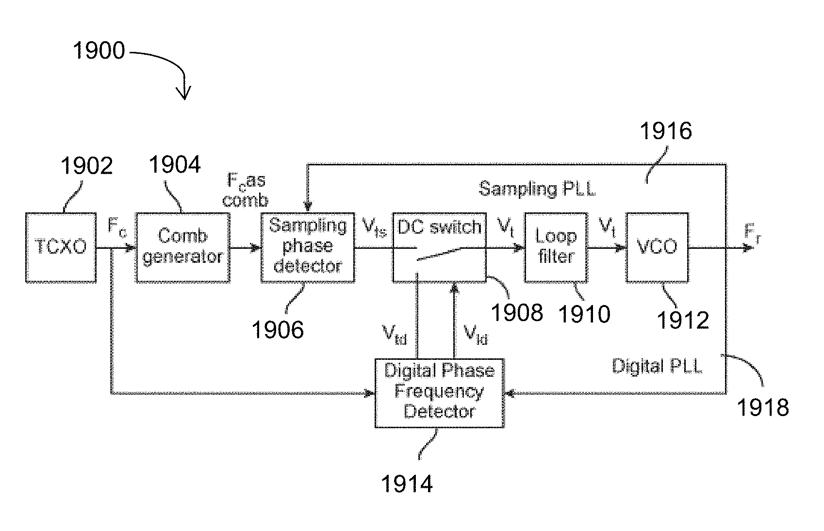
- In an additional embodiment of present disclosure, the ultra-low phase noise frequency synthesizer comprises one sampling PLL. The sampling PLL comprises one reference clock, one sampling phase detector, one digital phase/frequency detector and one VCO.
- According to an embodiment of the present disclosure a detection system comprising a RADAR unit and an ultra-low phase noise frequency synthesizer is provided. The system is made up of System on Chip (SoC) module. The RADAR unit configured for detecting the presence or imaging of one or more objects in one or more directions. The RADAR unit comprising: a transmitter for transmitting at least one radio signal; and a receiver for receiving the at least one radio signal returned from the one or more objects/targets. In an embodiment, the Transmit and receive signal frequencies might be equal. For example, if there is no Doppler effect, the signal frequencies may be equal. In an embodiment, the transmit and receive frequencies might also be different, for example in cases where the doppler effect is present. The ultra-low phase noise frequency synthesizer comprises one main PLL (Phase Lock Loop) and one reference sampling PLL. The main PLL further comprises one Fractional-N Synthesizer chip, one primary VCO (Voltage Controlled Oscillator) and one down convert mixer. The Fractional-N Synthesizer chip includes one Digital Phase Detector and one software controllable variable frequency divider. The reference sampling PLL comprises one sampling PLL, and one reference VCO. This embodiment provides multiple improvements in system output which are based on the following technical approaches—a) using of dual loop approach to reduce frequency multiplication number, b) using of sampling PLL to make its noise contribution negligible, and c) using of a high frequency Fractional-N Synthesizer chip in the main PLL.
- In an additional embodiment of the present disclosure, a vehicle having a detection and imaging system is disclosed. The detection and imaging system may be implemented for detecting information corresponding to one or more objects, the detection unit comprising: a RADAR unit for transmitting radio signals and further for receiving the returned radio signal(s) from one or more objects/targets; and at least one ultra-low phase noise frequency synthesizer for refining the returned signals to reduce the effect of phase noise in the returned radio signals. Further, the detection unit comprises a processor for processing the refined signals to determine one or more characteristics corresponding to the one or more objects, the processor determining one or more actions based on one or more factors and the one or more characteristics corresponding to the one or more objects. The processor further may determine one or more actions being adoptable by the vehicle based on one or more characteristics that may originate from the RADAR system and/or in conjunction with information originated from another sensor. The vehicle further includes one or more components communicably coupled to the processor for performing the determined one or more actions.
- The detection and imaging system may further include a memory for storing information and characteristics corresponding to the one or more objects; and actions performed by the vehicle.
- Hereinabove, the at least one ultra-low phase noise frequency synthesizer may be implemented in any manner as described further in the detailed description of this disclosure. Further, the RADAR unit comprises at least one of: traditional single antenna RADAR, dual or multi antenna RADAR, synthetic aperture RADAR, and one or more other RADARs. Further, in an embodiment, the processor may determine phase shift in frequencies of the transmitted radio signals and the returned radio signals. Such phase shift (difference in phase noise frequency) may further be analyzed in light of a frequency of the refined radio signal to self-evaluate overall performance of the detection and imaging system (or specific performance of the ultra-low phase noise frequency synthesizer).
- The preceding is a simplified summary to provide an understanding of some aspects of embodiments of the present disclosure. This summary is neither an extensive nor exhaustive overview of the present disclosure and its various embodiments. The summary presents selected concepts of the embodiments of the present disclosure in a simplified form as an introduction to the more detailed description presented below. As will be appreciated, other embodiments of the present disclosure are possible utilizing, alone or in combination, one or more of the features set forth above or described in detail below.
Dr. Tal Lavian offers insightful and decisive expertise as a telecommunications expert witness and network communications expert witness.